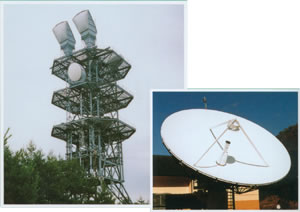
Antenna radio wave attenuation during rain
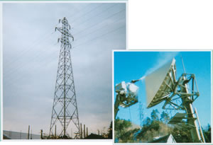
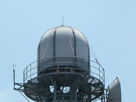
Examples of weather radar radomes
To mitigate damage from localized and torrential downpours, the Ministry of Land, Infrastructure, Transport and Tourism has installed XRAIN, an X-band radar (8-12 GHz) capable of high-resolution, near real-time observation.
While C-band radar (4-8 GHz) is suitable for wide-area observation, XRAIN can observe localized heavy rainfall in detail and in real time *1.
However, in the higher frequency X-band, the radio wave attenuation is greater due to the water film that forms on the radome surface.
A film of water forms on the dome surface due to rain.
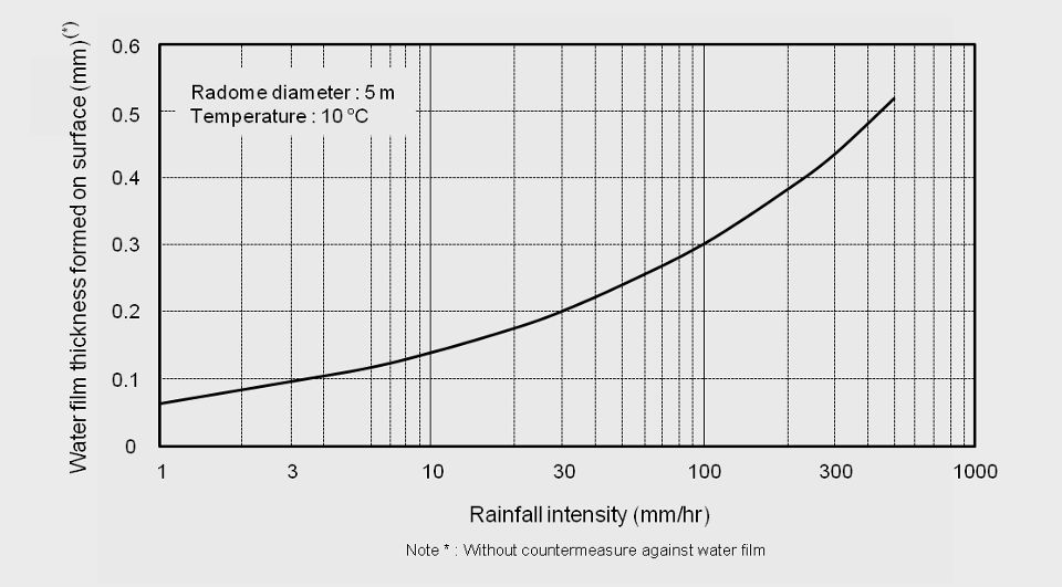
Even light rain can form a water film on the surface of the radome, causing signal degradation. The thickness of the water film varies depending on the intensity of the rain, the material of the radome, the surface condition, etc.
Figure 1 shows an estimate of the water film thickness that would form on a uniform, smooth, non-Super hydrophobic surface of a radome with a diameter of 5 m. For example, a rainfall of 30 mm per hour could result in a water film of 0.2 mm thickness forming on the surface.
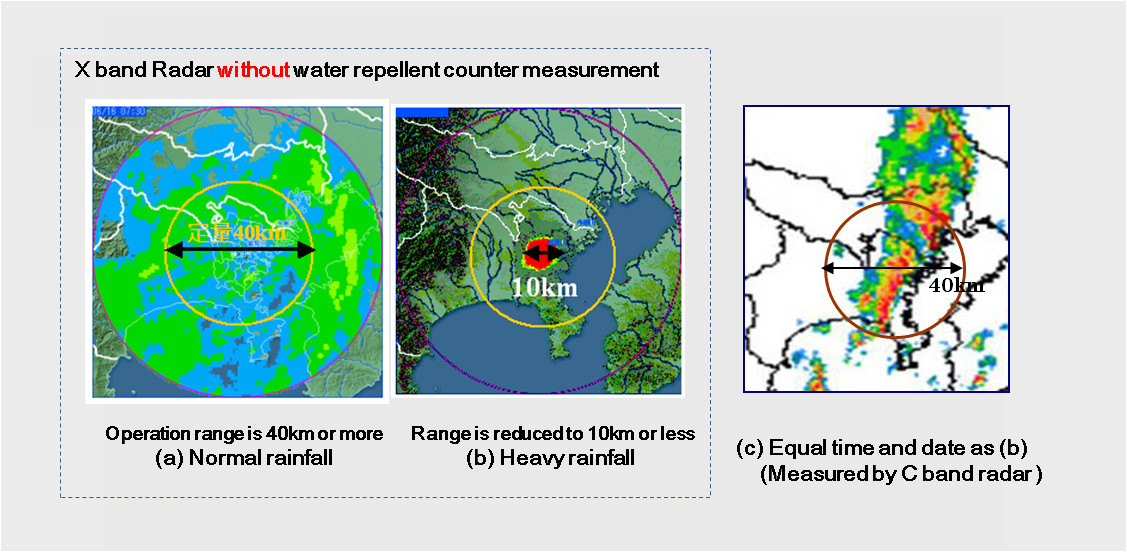
Without measures to prevent water film buildup, the operating range will be drastically reduced due to water film attenuation *3.
In fact, during periods of heavy rain, the signal reduction due to the water film on the radome became noticeable, resulting in an extremely narrow observation range.
For example, rainfall of 30 mm per hour can form a 0.2 mm thick water film on the radome surface, resulting in 5.0 dB of attenuation.
As shown in Figure 2, the observation range was narrowed from the usual 80 km to 10 km.
Key points for preventing water film buildup
By coating the radome surface with a Super hydrophobic material *3 that has a contact angle of 140 degrees or more, the formation of a water film can be suppressed.
Combining super water repellency and durability, HIREC® can achieve a contact angle of 150 degrees between the surface and water droplets.
Furthermore, it features a self-cleaning mechanism, allowing it to maintain water repellency for approximately three years.
HIREC® is used in XRAIN's X-band MP radar radome as a measure against water film attenuation.
*1) "Radar Observation of Precipitation for River Management in Japan," Ministry of Land, Infrastructure, Transport and Tourism, September 30, 2013, http://www.mlit.go.jp/river/pamphlet_jirei/pdf/xrain_en.pdf (1.7MB)
*2) "Research Report on Improving Attenuation Reduction Technology for 9GHz Band Weather Radar Radomes," Advanced Communications Technology Research Advancement Center, March 2009.
*3) "Study on Radome Attenuation Countermeasures for 9GHz Band Weather Radar," Advanced Communications Technology Research Advancement Center (AIST)
Examples of BS antennas
Antenna radio wave attenuation during rain
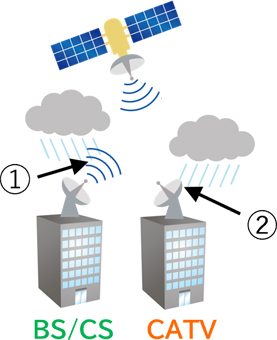
Figure 3: Relationship between rain and radio waves
② Caused by rain falling on the antenna water film Damping due to
Figure 3 is a schematic diagram showing how radio waves are attenuated by rain, using a BS antenna as an example.
The attenuation of radio waves during rainfall is not solely due to rain between the satellite and the BS antenna, that is, attenuation caused by raindrops in space.
There is something called water film attenuation.
Water film attenuation refers to the attenuation of radio waves caused by a water film that forms on a BS antenna due to rainwater.
Applying super hydrophobic coating HIREC to the surface of a BS antenna results in virtually no water film forming on the surface, significantly reducing water film attenuation.
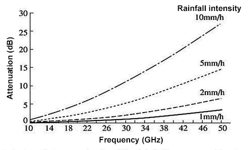
Figure 4 Relationship between rainfall intensity and rainfall attenuation
Figure 4 shows the relationship between rainfall intensity and rainfall attenuation.
Rainfall attenuation occurs when the operating frequency exceeds 10 GHz, and the amount of attenuation increases with higher frequencies. Furthermore, the amount of attenuation increases with increasing rainfall.
For example, in the 12 GHz frequency band used by BS (Broadcasting System), rainfall intensities of 5 mm/h and 10 mm/h result in rainfall attenuations of approximately 1 dB and 2 dB, respectively.
The figure above shows the relationship between frequency and water film attenuation, with water film thickness as a parameter. (Calculated based on the water film attenuation formula and complex dielectric constant data for water in Meteorological Research Note No. 112)
It has been found that water film attenuation occurs even at frequencies of a few GHz, and the amount of attenuation increases as the frequency and the thickness of the water film increase.
The thickness of the water film at a given rainfall intensity varies depending on the size and shape of the antenna, but we will introduce an example published in Meteorological Research Note No. 139.
At 10°C, in a radome shape with a diameter of 5m, a rainfall intensity of 10mm/hr resulted in a water film thickness of approximately 0.16mm. From this example, it appears that a water film of 0.1-0.2mm thickness can occur even with normal rainfall.
Furthermore, considering the degradation of the antenna surface due to ultraviolet rays, it is likely that the longer the outdoor installation period for the same antenna, the thicker the water film will become, even with the same amount of rainfall.
The rainfall attenuation data from Figure 4 and the water film attenuation calculation results from Figure 5 are summarized in Figure 6.
This shows that the effect of water film attenuation is not insignificant. In particular, water film countermeasures are important around 10 GHz and below.
By applying Super hydrophobic to the antenna surface to strongly repel water, radio wave attenuation caused by water film will be almost completely eliminated below 10GHz.
While rainfall attenuation does occur at frequencies above 10GHz, the water film attenuation can be eliminated, thus reducing overall attenuation.
Examples of rain protection measures for antennas
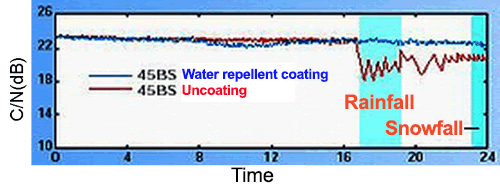
Figure 7 shows an example of measured radio wave reception characteristics using a BS antenna (12GHz band).
When comparing antennas with and without super hydrophobic coating HIREC, during rainfall (17:00-19:00), antennas without HIREC coating experienced approximately 3-4 dB of attenuation, while antennas with HIREC coating showed no attenuation.
Although the rainfall intensity is unknown, no attenuation occurred on the antenna painted with HIREC, so it is estimated to be 5 mm/h or less based on the graph of rainfall intensity and rainfall attenuation.
Furthermore, in the graph of rainfall intensity and rainfall attenuation, the rainfall attenuation in the 12GHz band at a rainfall intensity of 5 mm/h is approximately 1 dB. Therefore, the 3-4 dB attenuation in Figure 7 can be interpreted as water film attenuation, not rainfall attenuation.
Furthermore, the fact that attenuation still occurs after 7 PM, when the rain has stopped, supports the idea that it is water film attenuation caused by a water film still being present on the antenna surface.
In other words, this indicates that if it rains on the antenna, water film attenuation will occur for some time even after the rain stops. On the other hand, no attenuation occurs in the antenna coated with super hydrophobic coating HIREC, indicating that almost no water film is formed on the antenna surface.
Based on the above, super hydrophobic coating HIREC can be considered one of the promising countermeasures against water film attenuation.
Finally, there are reports that water film attenuation occurs even at frequencies below 10 GHz, but this is currently unconfirmed. We will add the latest information as soon as we have more details.
Snow countermeasures using Super hydrophobic sheets on antennas
Super hydrophobic sheets can be worn even in winter.
Traditionally, snow protection measures have mostly involved directly installing solutions on antennas and other structures, but a major challenge has been that on-site installation is impossible in winter due to low temperatures.
Therefore, we will introduce an example of Super hydrophobic sheet that enables snow protection for on-site equipment even in winter.
- Advantages of Super hydrophobic sheets
-
- Can be installed even in winter ← On-site painting of the antenna at temperatures below 5°C is not possible.
- Can be installed in 1-2 hours ← At least 2 days required for on-site installation of the antenna
- Disadvantages of Super hydrophobic sheets
-
- Approximately 1 year life (depending on the weather resistance of the sheet material) ← Approximately 3 years for conventional on-site painting
* Super hydrophobic sheet material: Polyethylene (PE) or polyester
* Super hydrophobic covers are made to order. Please contact us for details.
The structure and practical application of Super hydrophobic sheets
- Reflector: Super hydrophobic sheet
-
- A polyethylene or polyester sheet (blue area) is coated with super hydrophobic coating [HIREC primer (light green area) and HIREC 100 (red area)].
The photo on the right shows Super hydrophobic sheet attached to the reflector part of the antenna.
- A polyethylene or polyester sheet (blue area) is coated with super hydrophobic coating [HIREC primer (light green area) and HIREC 100 (red area)].
- Converter (radio wave collecting section): Only the HIREC100 (red part) is painted with a brush.
-
- HIREC100 is a functional material, not a paint, so brushing it will leave brush marks (unevenness). These white unevenness marks are evidence of its excellent water repellency. (Converter enlarged view)
*HIREC100 is the predecessor to HIREC-R. The performance of both products is equivalent.
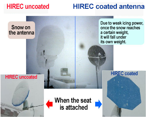
Comparison of radio wave reception status with and without Super hydrophobic during snowfall.
We would like to introduce a comparative experiment conducted during snowfall.
- Super hydrophobic repellent untreated antenna
- Water film formation → Poor reception
- HIREC Super hydrophobic repellent antenna
- Suppresses the formation of a water film → Normal reception
(Approximately 40 cm of snow fell in the half-day period up to 8:00 AM)
Radio wave reception status of BS antenna during snowfall (Situation about 14 months after installation of BS antenna)
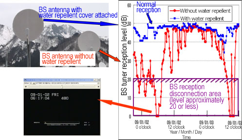
(January 1, 2009, 7:00 PM - January 3, 2009, 12:00 PM; Location: Yuzawa, Niigata)
With an antenna that had not been treated Super hydrophobic, reception interruptions (tuner reception level below 20) occurred several times.
With the antenna fitted with Super hydrophobic cover (the converter also had Super hydrophobic coating), there was a decrease in signal strength, but reception was still possible.
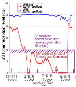
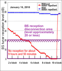
Radio wave reception status of the BS antenna during snowfall (approximately 26 months after antenna installation)
- Super hydrophobic untreated BS antenna
- With BS antennas that were not treated with Super hydrophobic, reception was impossible (reception level below 20) or image distortion was observed for several tens of minutes to nearly 9 hours per day during the 54-day recording period.
The frequency was 15 times. - Super hydrophobic repellent BS antenna
- With Super hydrophobic repellent BS antenna, the reception level was never below 25.
Detailed example of radio wave reception
It can be inferred that the reason BS broadcasts were received successfully was because almost no water film formed on the Super hydrophobic treated antenna and converter section.
While snow-melting devices exist to prevent snow accumulation on antennas, the main cause of radio wave attenuation is water (water film), not snow or ice. Therefore, antenna snow-melting devices may not be effective in reducing radio wave attenuation.
Communications and broadcasting related
- antenna
- radome
- radar
- steel tower
- others
Electricity and energy related
- steel tower
- antenna
- tank
- others
Meteorology and Astronomy Related
- Weather radar
- Anemometer
- rain gauge
- others
Construction-related
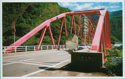
- bridge
- tunnel
- others

others
- sign
- traffic light hood
- Anti-condensation measures
- Water measures
- measures against snow
- Measures against ice adhesion
- Icicle measures
- others